High Aspect Ratio
High stretch (AR = 18) keeps the induced drag low.
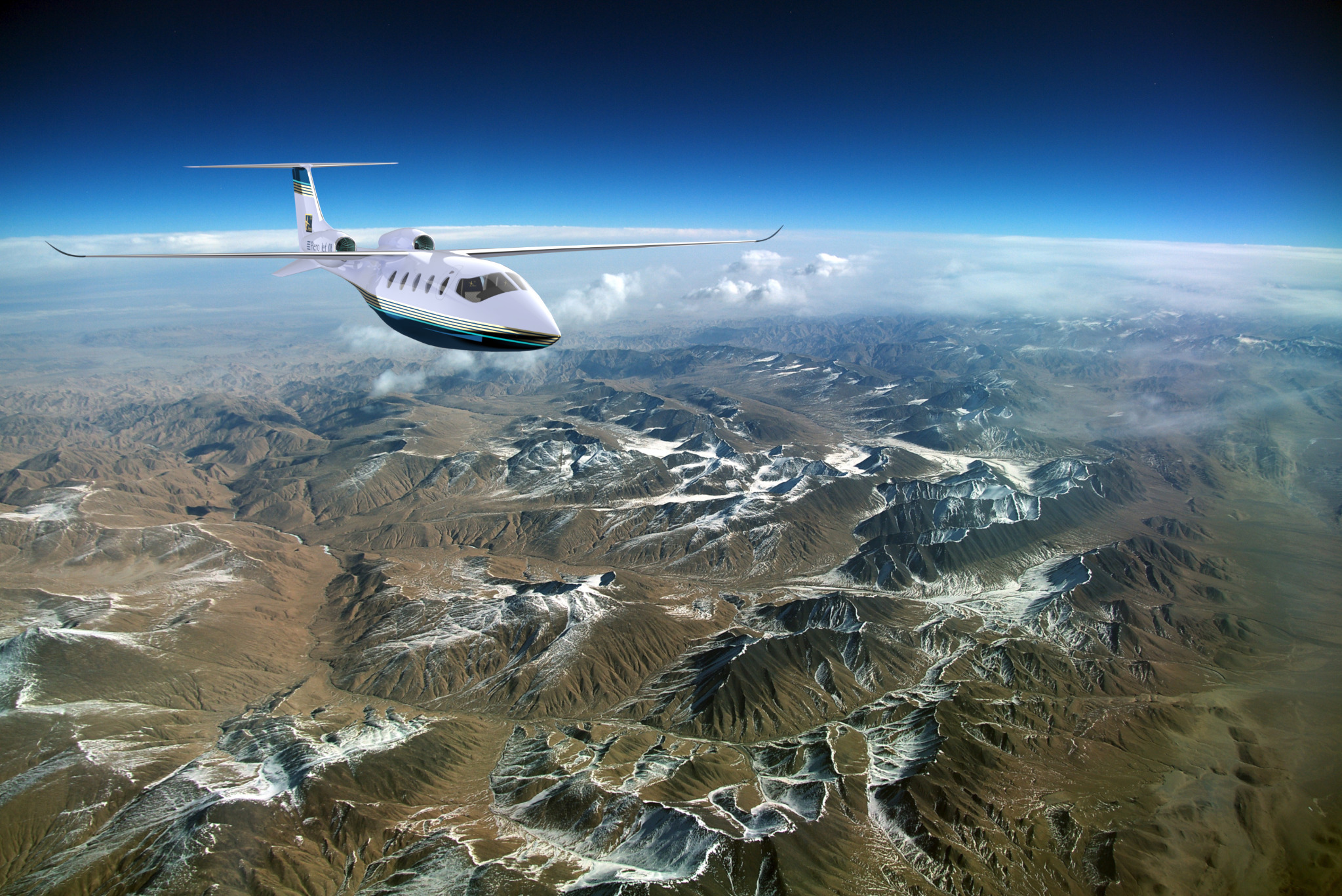
High Altitude Flying in the low density low friction environment around FL500.
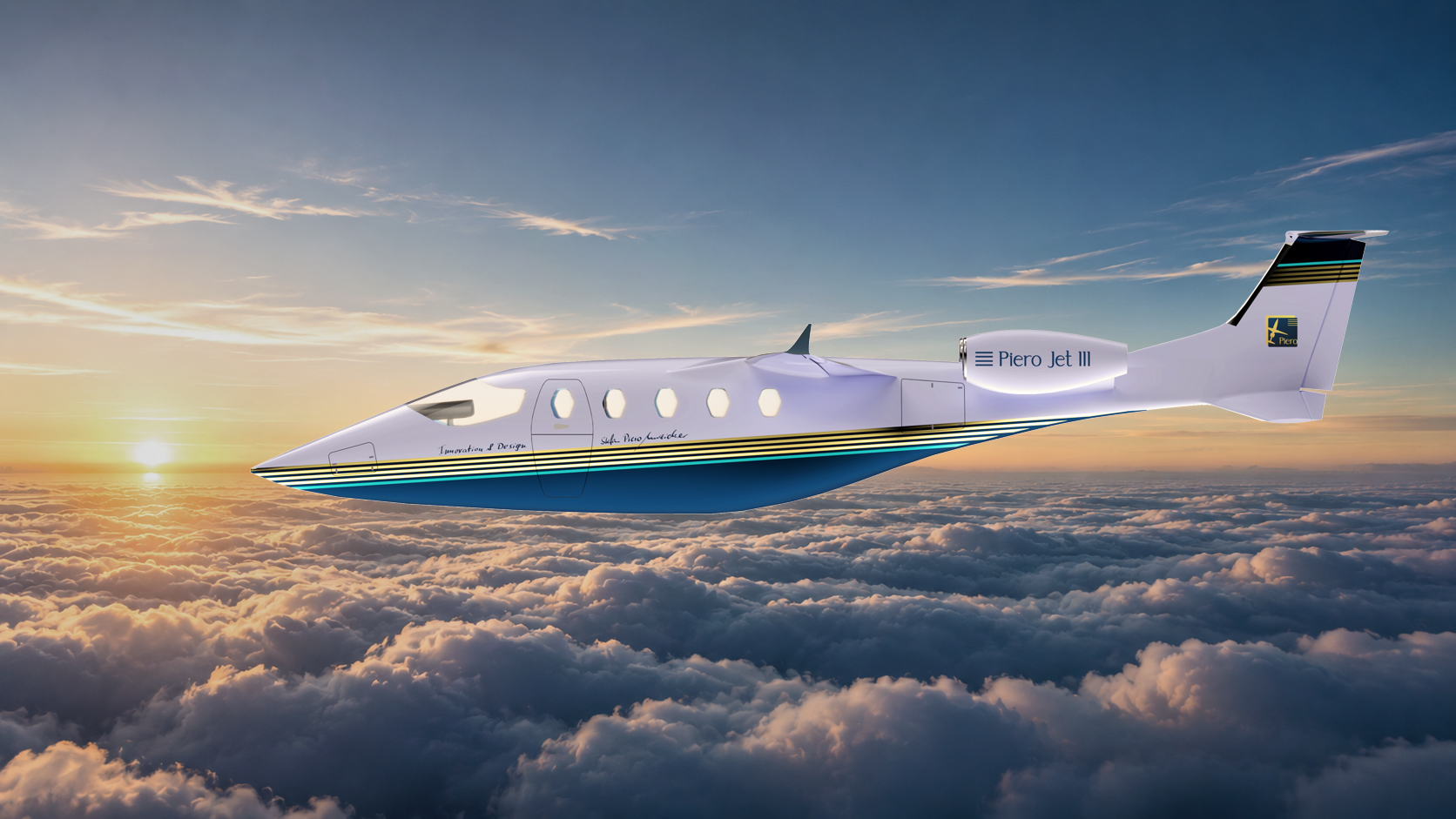
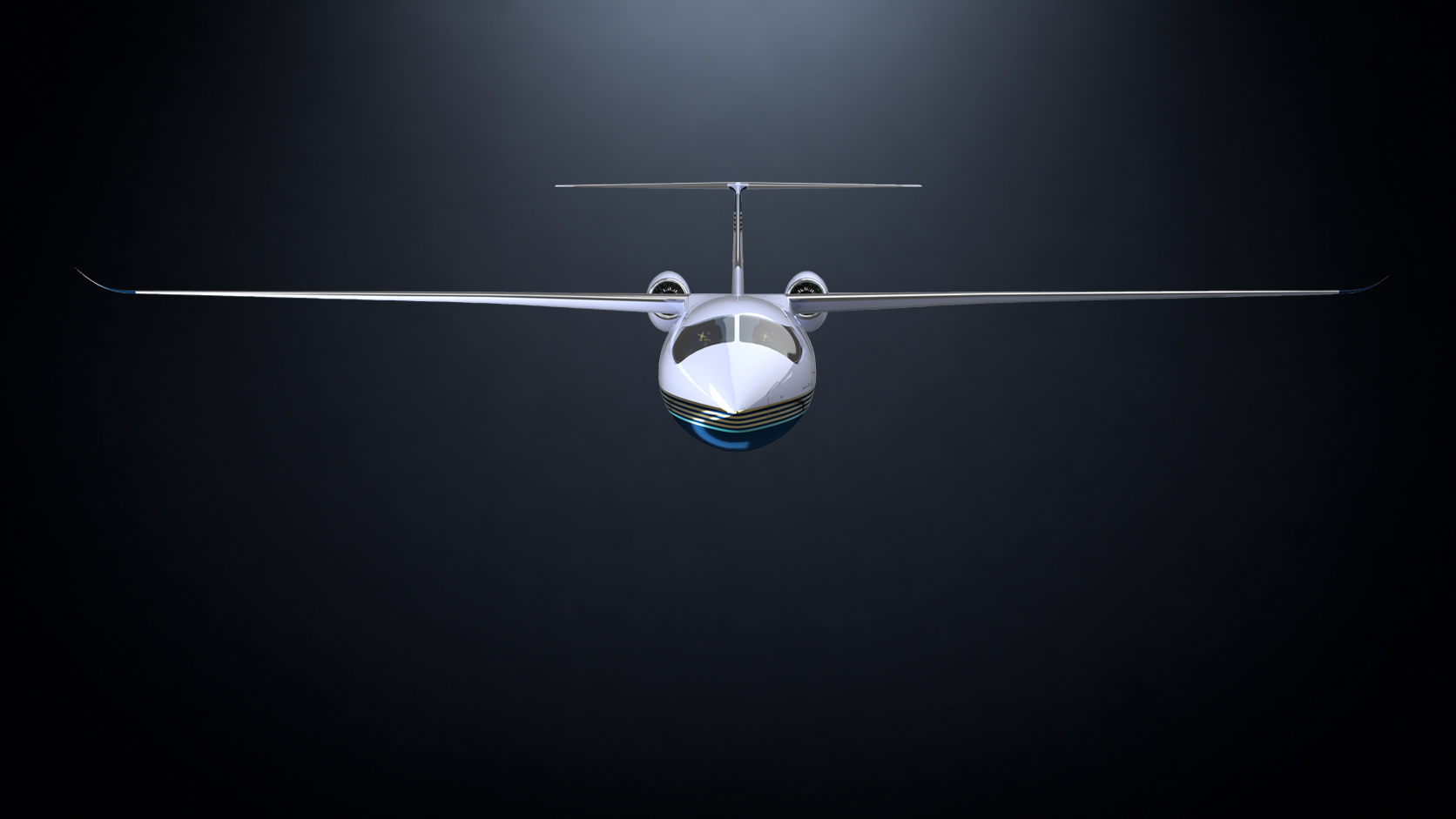
High stretch (AR = 18) keeps the induced drag low.
High Altitude Flying in the low density low friction environment around FL500.

The straight wing provides more lift than any swept wing for a given wing area. The required wing size for a given weight and a given altitude is at its minimum if the geometry is straight. For a given engine power the straight wing is the fastest with the lowest drag. The wing route bending- and torsion moments are minimized likewise leading to a lightweight design.
The “Top Wing” configurations is less prone to shed vortices/induced-drag from the fuselage if designed well. Combined Lift Effects at High AOA especially with Slats and Flaps extended can be designed to significantly higher Lift-Coefficients. That may be the main cause why Darwin had the birds grow their wings on top.
Back to contents ↑

Large aircraft automatically provide large space for fuel accomodation since
Volume ≃ L³.
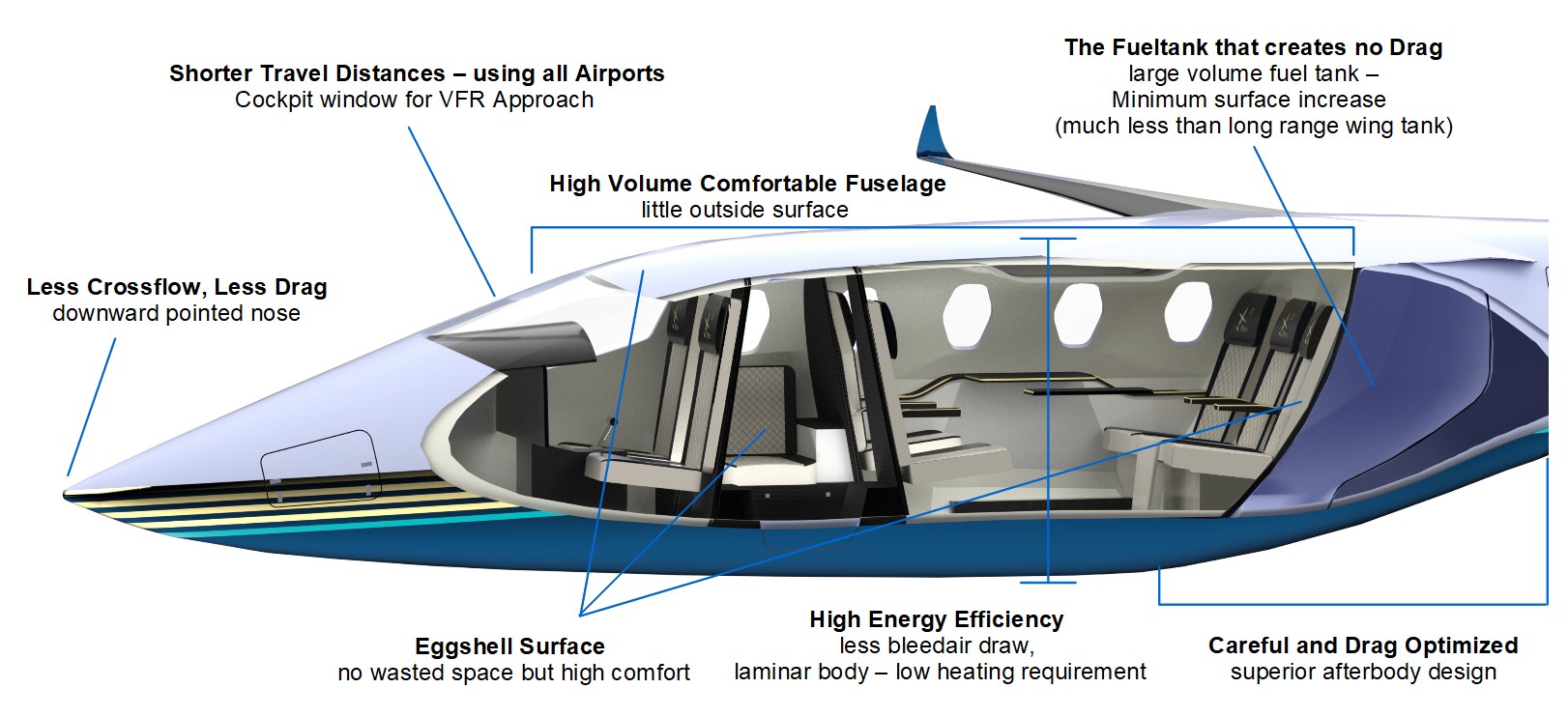
For a small aircraft with large fuel requirement, the wing or wing tanks become over-proportionally bulky. Wing decoupling for fuel requirement is one of the keys to success. The fuselage itself offers a large geometry for such a main tank. Little additional surface is hereby generated particularly if such fuel tank can be located near the largest cabin prosection area.
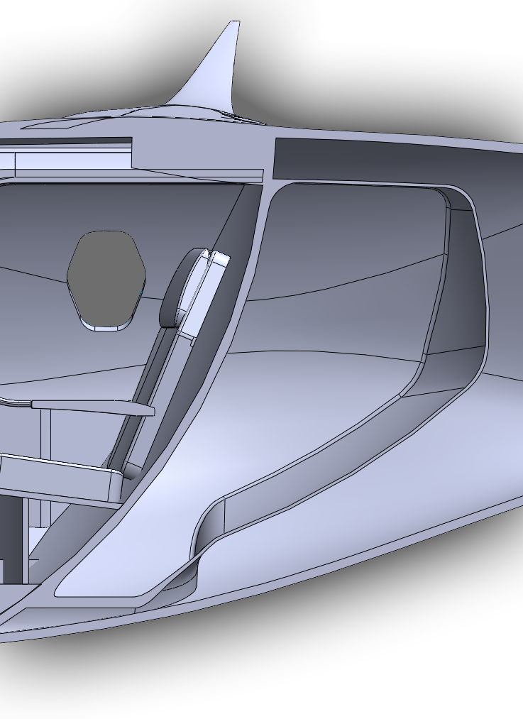
If one needs bring a large amount of fuel in a relatively small aircraft, a new location concept inside fuselage becomes crucial.
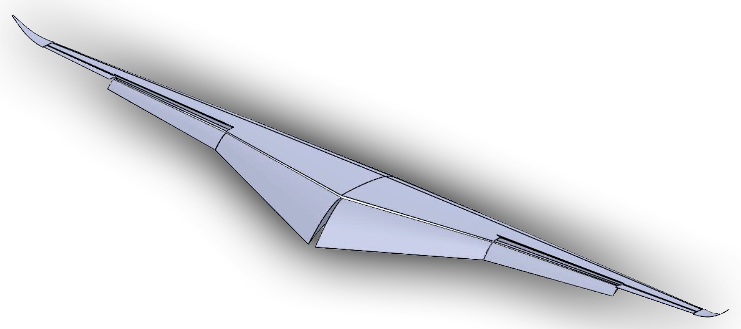
A wing only driven by aerodynamics and stress analysis can be designed slender and thin.
Needless to say The PJ III also uses – like industry standard - a laminar & supercritical profile, to achieve the speed of M=.76
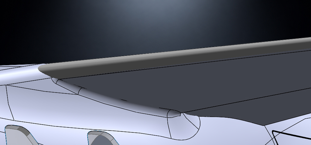

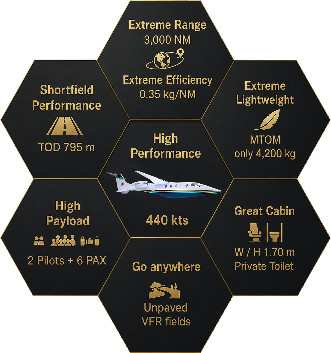
Short chord (MAC 0.85 m) keeps the Reynolds number small, reduces boundary-layer thickness and therefore minimizes skin-friction and parasite drag.
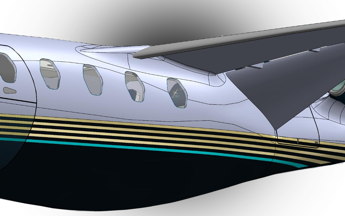
The fuselage shape is coupled with the wing and its high-lift devices to achieve efficient short-field performance.
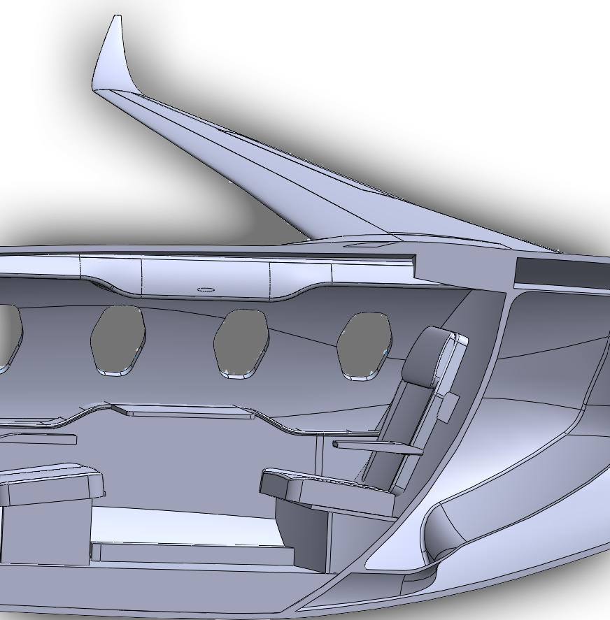
Relocating the main fuel volume from the wing into the fuselage enables the slender, high-altitude wing configuration.
| Aircraft | Weight [kg] | Range [nm] | Max Fuel [L] | TOD |
|---|---|---|---|---|
| Citation Mustang | 3,930 | 1,343 | 1,446 | 948 |
| Citation M2 | 4,853 | 1,300 | 1,862 | 978 |
| Phenom 100 | 4,800 | 1,178 | 1,556 | 975 |
| Eclipse Jet | 2,722 | 1,295 | 950 | 742 |
| Honda Jet | 4,854 | 1,437 | 1,638 | 1,172 |
| Piaggio Avanti | 5,489 | 1,470 | 1,550 | 994 |
| Average | 4,441 | 1,337 | 1,500 | 961 |
| PJ III | 4,200 | 3,050 | 1,800 | 795 |
| Aircraft | Weight [kg] | Range [nm] | Max Fuel [L] | TOD |
|---|---|---|---|---|
| Citation Sovereign | 13,959 | 3,200 | 6,435 | 1,076 |
| Legacy 500 | 17,400 | 3,125 | 7,900 | 1,245 |
| Challenger 300 | 17,622 | 3,100 | 8,100 | 1,466 |
| Average | 16,327 | 3,142 | 7,478 | 1,262 |
| PJ III | 4,200 | 3,050 | 1,800 | 795 |
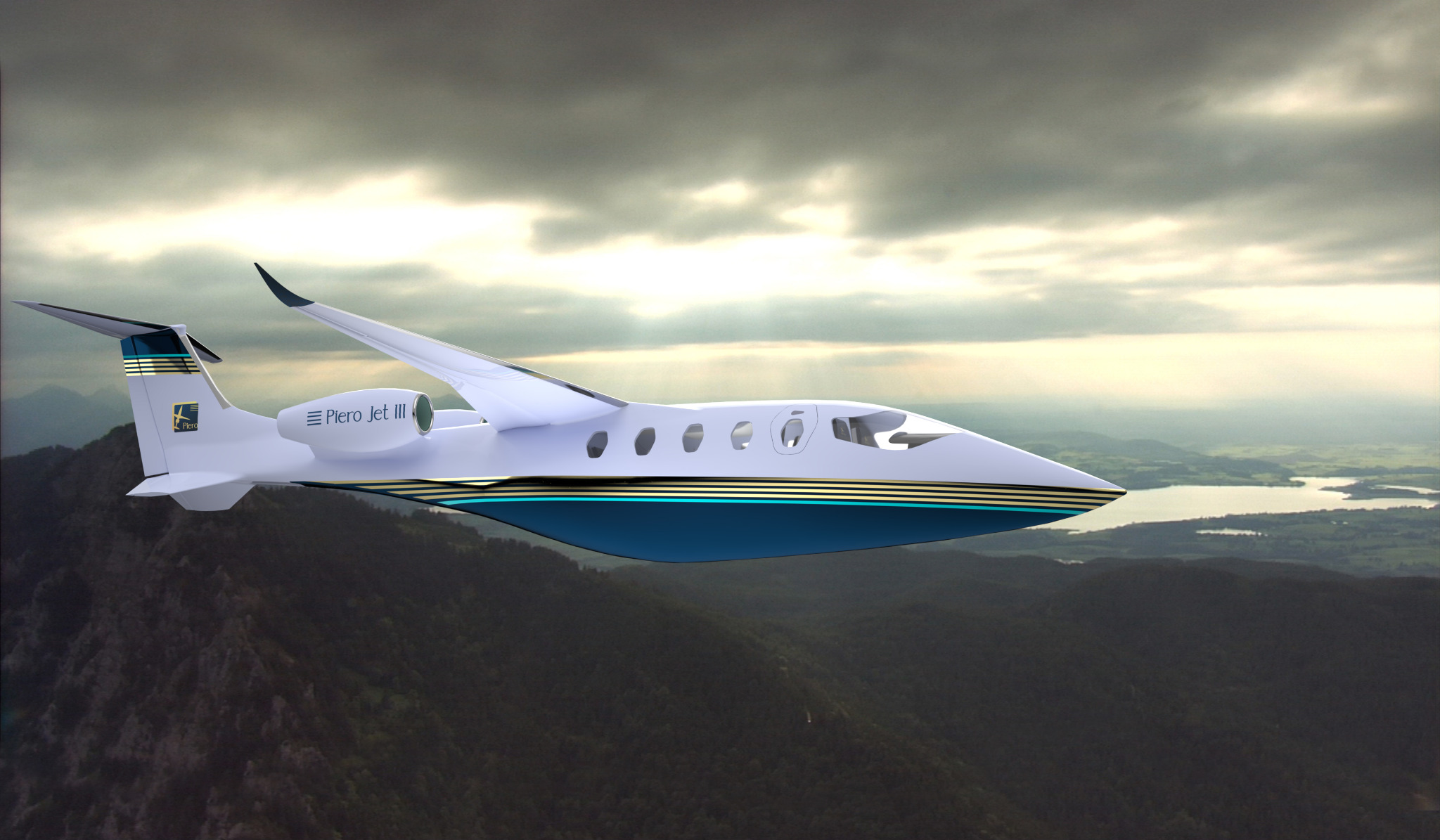
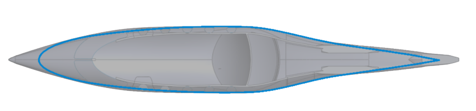
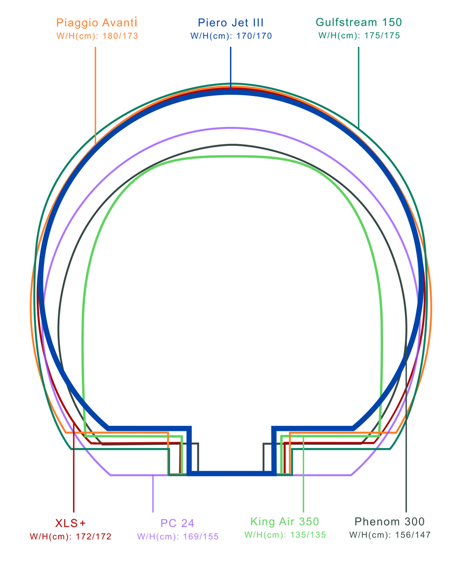
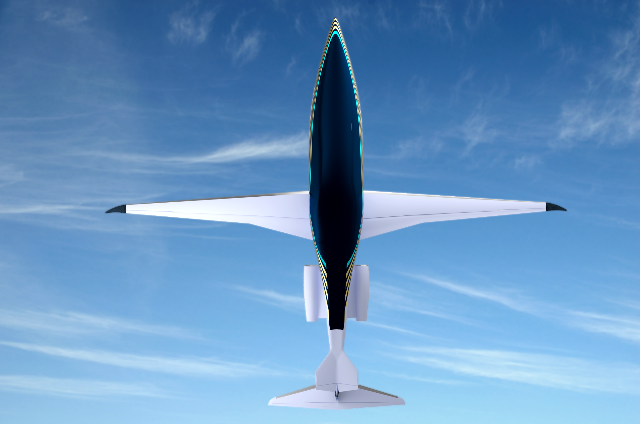
A laminar profile is transformed into a three-dimensional body of revolution.
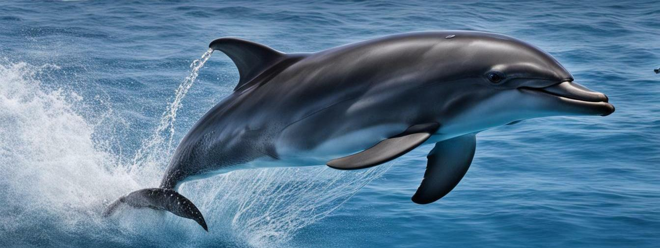
Nature uses non-cylindrical shapes based on continuously changing, streamlined body sections.
Cylindrical forms are avoided for a reason.
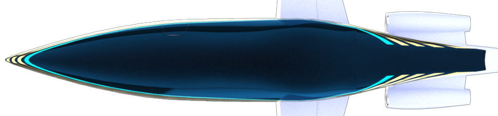
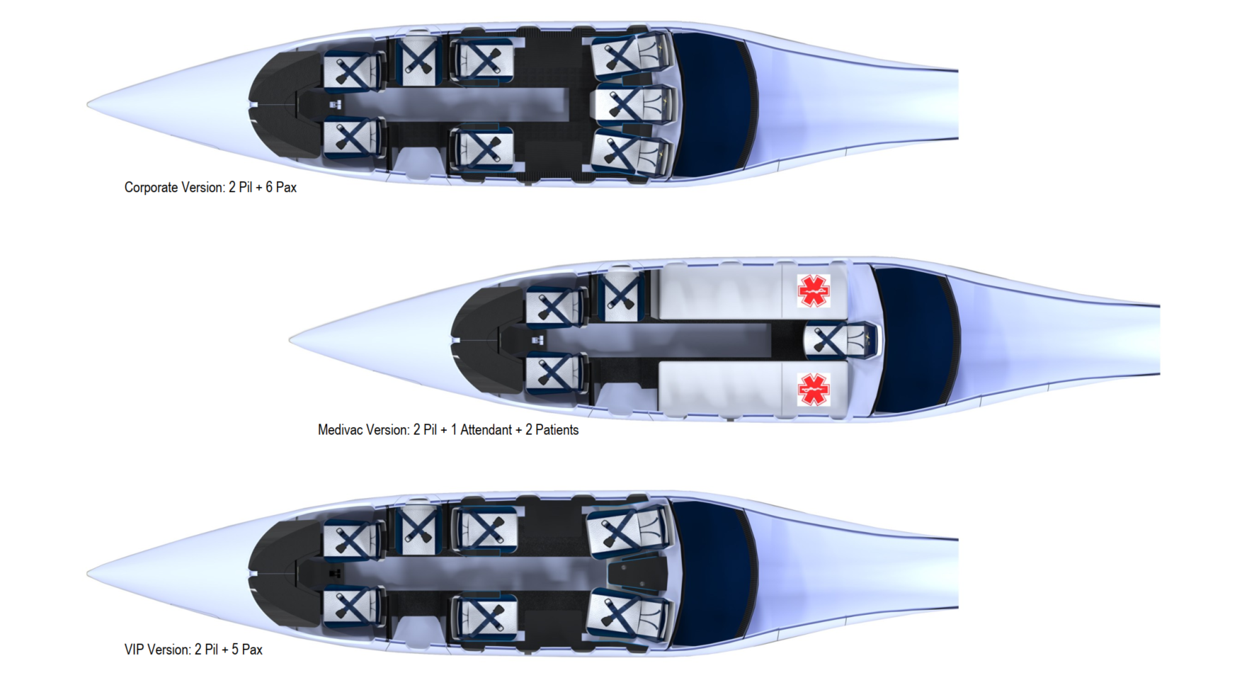
The resulting fuselage geometry follows the same aerodynamic principle, shown here in a view from below.